MIG welding has been in use since the 1940s and remains to be very useful today. Metal Inert Gas or MIG welding is also known as GMAW or Gas Metal Arc Welding. The name “MIG welding” is more widely used.
What is MIG Welding?
MIG welding is basically using heat to melt metal and use it to join 2 metal pieces together. This welding process has many uses, from simple home applications to major industrial functions. It is used to weld or join together a wide range of different kinds of metals. It can weld various alloys including stainless steel, magnesium, nickel, aluminum, carbon steel, silicon bronze and copper.
Advantages of MIG Welding
This welding process has been around for a long time because of its many advantages. Some of these are:
- Allows for joining several different metals of different thickness
- High quality welds in a shorter time compared to TIG or SMAW welding
- Gives better weld bead
- Has minimal weld splatter, which is easy to remove
- Minimal slag entrapment in weld metal (because no flux used)
- Alloying element loss is minimal (due to gas shield that protects the arc)
- Welds are clean
- Produces very little smoke
- Fast and cheap production
- Allows for long welds with fewer restarts
- Continuous welding wire, with reduced downtime required for electrode replacement
- Great choice for making spot and tack type of welds
Disadvantages of MIG Welding
This welding technique comes with a few limitations, like these ones:
- Welding is limited to metal thickness ranging from thin to medium thick only
- Cannot be used to weld materials from an overhead or vertical position because of high heat input involved and the weld puddle fluidity (can put the welder at high risk of burning and getting dripped on by the weld puddle from this position)
- Equipment is easy to learn but is a bit more complex than shielded metal-arc welding equipment
- Welder will have to work near the MIG welding machine
- Wind can be a major problem when working with the MIG machine outdoors (may blow the wet weld puddle around)
- Constantly requires a bottle of gas
- Needs clean joint
- Contact tip very prone to splatters that cause seizing up
- Too many parts, making troubleshooting for malfunctioning parts annoying and time-consuming
Basic welding process
How an MIG weld works is pretty simple. It has 3 basic requirements- electricity, electrode, and shielding gas. Electricity produces heat while the electrode fills the joint. The shielding gas acts as a shield for the weld against the air.
The electrode used in MIG welding is very small. It has to be fed continuously. The welder will have to control how much weld will be used.
Arc vs MIG vs TIG – A brief comparison
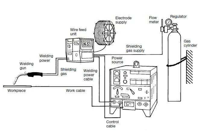
MIG Welding Basic Equipment
The basic equipment includes a number of parts, each working towards making a good, clean weld.
The welder
Inside the welding machine is a spool of wire, with a series of different rollers. These rollers will push the wire out and into the welding gun. This is the part to check and fix if a wire jam happens (which is not very often, but does happen from time to time).
The tension nut should be holding the large wire spool. This nut should be tight enough to prevent the wire from unravelling. However, make sure it is not too tight that the rollers can no longer pull the wire out from the spool.
The gas tank
A MIG welder will have a gas tank at the back of the equipment. This tank may contain either a combination of CO2 and argon or just pure argon. The gas will shield the weld while it is formed. If no gas is used, the weld will appear brown and splattered. The weld will not look as nice and smooth as when using gas.
Before using the MIG welder, turn on the main tank valve. Check that there is gas in the tank. Look at the gauges. It should read between 0 and 2500 PSI. The regulator should read between 15 and 25 PSI, depending on the set up and the welding gun type being used.
The welding gun
This is the part of the MIG equipment that gets the main attention during the entire welding process. The welding gun has a trigger. This will control the flow of electricity and the wire feed. At the tip of the gun is a replaceable copper tip. This guides the wire as the weld is formed. The tips come in various sizes, designed to fit the wire diameter.
The gun exterior is covered by a metal or ceramic cup. This protects the electrode and directs gas flow as it exits through the tip of the welding gun. A small piece of the wire can be seen sticking out from the tip of the welding gun. This is normal.
The ground clamp
This is the cathode or the negatively charged portion of the circuit. The ground clamp completes the circuit composed of the welding gun, welder, and the work piece.
The ground clamp should be clipped onto the welding table or directly to the metal work piece. Make sure that the clamp have good contact with the metal piece that is being welded. If not, then the MIG welder will not work. Check that there are no paint or rust preventing the ground clamp from making good connection with the metal work piece.
Voltage and polarity
There is only one type of voltage and polarity used in a MIG welder. Voltage is a direct current (D/C), similar to one used in car batteries. The direct current will flow in only one direction, from a negative point to a positive end.
MIG welders use a D/C electrode positive (+) polarity. This is the standard. The handle serves as the positive terminal of the entire circuit. Electricity will flow from the metal and into the welding handle.
The power source is also referred to as the constant voltage power supply. The voltage is being adjusted and controlled in the MIG welding process.
Electrodes
In selecting the correct electrode or wire for MIG welding, the kind of wire should match the kind of metal being worked on. Other considerations include the position of the metal to be welded, resistance to abrasion, and the type of transfer.
The commonly used electrodes for MIG welding are solid wires. The diameters range from 0.023 to 0.045. For heavier applications such as in industrial applications, thicker wires are used. Common sizes used are 0.023, 0.030, 0.035 and 0.045.
The shielding gas
This is another vital component of MIG welding. The shielding gas is fed through the gun and then suffocates or entirely covers the weld area. It acts as a protective cover that shields the weld from the air. Inside this enclosed air-free zone will be the filler wire and the welding arc – both do the work in welding the joint together.
In MIG welding, 3 types of shielding gases are used:
- Carbon dioxide (CO2)
- Argon (Ar)
- Helium (He)
These are used alone, such as with 100% argon for welding aluminum, or in certain combinations, such as with argon and CO2 for stainless steel welding. The choice of shielding gas depends on the compatibility to the base metal and the electrode. If incompatible, the weld will not form properly or will not be strong enough to hold the joints.
The type of shielding gas used will also determine the following results of the welding process:
- How deep will the weld penetrate the base metal being welded
- Mechanical properties of the finished weld
- Welding arc characteristics
Basic MIG Welding Procedure
- Take the fume extractor and move it over the area to be welded. When turned on, the extractor will automatically start if fumes are detected.
- Attach the ground clamp to any metal surface that can adequately provide a ground.
- Check that the adjusting screw is loose.
- Use the handwheel to open the cylinder. The welder’s hand should be around the wheel. This is for easy access in case a deficiency occurs and components are released while under high pressure. When fully opened, the pressure gauge will change from 0 to a certain value. The maximum value will be 2500 PSI. Adjust to a little more than 1000 PSI. This level is enough for welding purposes.
- Turn the adjusting screw in a clockwise direction until the gauge needle goes to 10-15 CFH.
- Set up the weld settings. See the directions placed in a panel located at the left side of the MIG welding unit. Use this chart to set the wire speed and the voltage.
- Power up the welder.
- Adjust the settings for the voltage and wire speed. Refer to the chart mentioned in step #6.
- Check that there is enough wire in the welding torch.
- Start welding. It may be better to practice laying a bead first.
- Once the weld is done, adjust the wire feed settings to the lowest level.
- Turn the gas cylinder valve off.
- Depress or squeeze the trigger on the weld gun to bleed the regulator. Keep bleeding until the CHF reading reaches the lowest level.
- Unscrew the adjusting screw. Turn until the screw becomes completely loose.
- Turn the welder off.
- Remove or detach the ground clamp.
- Coil all of the attached wires neatly.
Tips to Welding With an MIG Welder
To create a good, functional and strong weld, take these expert tips:
- Make sure that there is adequate clamping and fixturing. The fixturing must be able to hold the work piece and keep it firmly in place. This will greatly minimize weld distortion. The fixturing must also be easy to load and unload.
- Establish a good connection between the workpiece (or the fixturing) and the ground clamp (work lead). The direction of the ground is also important, especially when working with steel or other ferromagnetic materials. The best position is away from the connection of the work lead.
- Electrode position is also vital to get the desired fusion, weld bead geometry and joint penetration.
- Check that all the connections of water and gas are tight and no leaks are present. Air or water entering the shield gas will create erratic arc operation and weld contamination.
- Set the flow rate of shielding gas according to the recommendation for the material being worked on. The size of the gun nozzle should also be according to the recommendations for that metal. The joint design will also determine the nozzle size and the gas flow rate. Higher gas flow rates are required for joint designs that include long distances between the nozzle and the work piece. For size, smaller nozzles are used for welding in the root of thick joints or in confined areas.
- To maintain good electrical contact between the contact tube and electrode, the contact tube must be periodically replaced.
MIG Welding Procedure
Laying a metal bead
This is a critical step in welding and this needs a little practice to create a good bead. For beginners, it is important to practice running a bead first. Just take a piece of scrap metal and make a weld on its surface. This step will also help even with skilled welders.
Laying beads first on a scrap metal helps to get a feel of the welding machine. This is also an opportunity to make the necessary adjustments in the power settings and to determine the best wire speed to use.
If the power setting is too low, the weld will be splattered. It will not be able to penetrate deep enough into the work piece. If the power setting is too high, the welding gun would likely meld the metal through.
Laying a bead is easy to learn and master. Position the nozzle of the weld gun over the metal surface. Make a small zigzag or small concentric circles. Start from the top of the weld and move slowly downwards.
When laying beads on the actual weld, do so in batches. Lay 1- to 2-inch long beads first. Laying beads that are too long will cause that area to heat up. This will cause warping. This will also compromise the strength of the weld area. It is better to weld one spot a little then move on to another spot. Then, come back and weld the area left in between.
The right welding settings
There is no exact welding settings for every occasion. It depends on the material, amount of weld, and a whole lot of other factors. The result of the bead and the effect on the metal pieces are good determinants if the settings are just right.
For instance, if holes show up in the work piece during welding, the power settings are turned too high. If the welds form in spurts (splatters), either the power or the wire speed is too low. The gun feeds bunches of wire out of its tip, makes contact, melts, and then splatters. This will not form a proper weld.
Adjust until the weld comes out and looks smooth and nice. Another sign of having the right welding settings is through the sound. A continuous sparking should be heard, signifying a good weld quality.
How to MIG Weld Aluminum
In MIG welding aluminum, a few adjustments will be necessary because this metal is softer. The feed wire will have to be larger. Power supply will have to be controlled more because aluminum is a better heat conductor. The electrode’s feed rate should also be controlled more.
- Choose a more powerful welding machine that can handle a thicker metal.
Aluminum with thickness of up to 1/8 of an inch (3 mm) can be well handled by a 115-volt welder. For aluminum with thickness of up to ¼ of an inch (6 mm), a 230-volt welding machine can do a good job.
- Select the right shielding gas
The shielding gas required for welding aluminum is pure argon. New hoses are not required although regulators specific for CO2 will have to be replaced when welding aluminum.
- Select the correct electrode
The thickness of the electrode is critical when working with aluminum. The choices are extremely narrow. It is more difficult to feed a thinner wire. Greater current is needed to melt a thicker wire. For aluminum welding, the electrodes should have a diameter of less than 1 mm (0.035 of an inch). One good choice is 4043 aluminum. Harder alloys such as 5356 aluminum will be easier to feed. However, these alloys will need more current to melt.
- Feed electrodes
The electrodes will be fed using an aluminum feeding kit. This type of kit can be purchased to make feeding soft aluminum wires easier. An aluminum feeding kit has these features:
- Contact tips with larger holes to accommodate the expanding aluminum when heated. The holes are larger but still small enough to allow good electrical contact.
- Drive rolls come in a U shape. The guides for the outlet and the inlet are shaped in a way that soft aluminum wire will not get shaved as it passes. The V shaped drive roll used for welding stainless steel is designed to intentionally shave the wire.
- Liners are non-metallic. This will cause a further reduction in friction as the wire passes through the feeder.
- Keep gun cable straight
Kinks happen more often with softer wires. This is mainly a result of the feeding restrictions. To avoid kinks, the gun cable should be kept as straight as possible for proper wire feeding.
How To Weld Aluminum Using TIG?
How to Weld Stainless Steel
Welding stainless steel is one of the most common welding projects. To properly MIG weld stainless steel, follow these guidelines:
- Choose the best method for joining base metals.
Commonly used joining methods include edge, T, butt, corner and lap. Consider the thickness of the base metals when choosing which method to use. Other considerations include required strength from the welded metals and joint accessibility.
- Secure the metals to be welded using jigs and fixtures.
- Select the appropriate welding process.
- Select the compatible inert shielding gas.
For stainless steel, the shielding gas is a mixture of CO2 (carbon dioxide) and argon.
- Select the filler metal.
Check the composition of the base metals. If the metal pieces to be welded are of the same metal composition, the filler material should be of the same composition, too. If the metal pieces to be welded are not of the same material, then choose the metal composition least likely to crack. Check that the filler material with the closest metal composition is compatible with both metal pieces to be welded.
- Clean the base metal.
Take the stainless steel base metal and gently brush the surface. Cleaning reduces the potential for oxides to form on the surface of the base metal pieces.
Use a stainless steel wire brush and gently brush the entire surface of the base metal. Brush until burrs and any oxides are removed.
When handling and preparing the base metal, wear gloves. This will keep the oils from the hands from transferring on the base metal. Oils can be places for oxidation to occur.
- Stainless steel should be at room temperature.
To get the best results, stainless steel should be at room temperature at the time of use. Preheating the stainless steel is not necessary, though, if it is austenitic. Stainless steel classified as ferritic or martensitic would have to be preheated. Stainless steel with high carbon contents or particularly thick also need to be reheated.
- Apply the welding torch.
- Subject the weld to post-heat after welding.
Do not allow stainless steel to be subjected to a rapid cool down. This will cause high internal stress that contributes to cracking. Post-heat is especially necessary when welding 2 thick metal pieces.
- Remove slag
If there is a slag, remove it with a chipping hammer or by grinding. This improves the appearance of the finished weld and make it more durable.
Now that you have the basics of MIG welding, time to take a deep breath and start actually welding something. It takes actual experience to get a feel of the entire welding process and really learn what works with a certain material and what does not.
Also may like: How To Weld A Galvanized Steel?